Thursday, August 25, 2011

OBIEE Publisher 11g - Performance Monitoring and User Auditing

BI Publisher performance monitoring enables you to monitor the performance of queries, reports and document generation and to analyze the provided details. User auditing provides information about what users logged in, when, how many times, what reports they accessed, and other actions they took within the application.


Enabling Monitoring and Viewing the Audit Log


To enable monitoring:
1. Update properties in the BI Publisher server configuration file.
2. Copy the component_events.xml file to your Middleware Home.
3. Configure the Audit Policy Settings with Fusion Middleware Control (Enterprise Manager)
4. Restart WebLogic Server.

To View Audit Log:
5. Configure Audit Repository
6. Create Data Source in WebLogic Server
7. Register the Audit-Storing Database to your Domain
8. Create Auditing Reports

1. Update Properties in the BI Publisher Server Configuration File

Three properties from the configuration file ‘xmlp-server-config.xml’ needs to be updated, the default location of the file is “config/bipublisher/repository/Admin/Configuration/xmlp-server-config.xml”.
Set: MONITORING_ENABLED = “true” and AUDIT_ENABLED = “true”, add a new property AUDIT_JPS_INTEGRATION = “true”. Below is a sample xmlp-server-config.xml file.
Before update
After Update
<'xmlpConfig xmlns="http://xmlns.oracle.com/oxp/xmlp">
   <'property name="SAW_SERVER" value=""/>
   <'property name="SAW_SESSION_TIMEOUT" value="90"/>
   <'property name="DEBUG_LEVEL" value="exception"/>
   <'property name="SAW_PORT" value=""/>
   <'property name="SAW_PASSWORD" value=""/>
   <'property name="SAW_PROTOCOL" value="http"/>
   <'property name="SAW_VERSION" value="v4"/>
   <'property name="SAW_USERNAME" value=""/>
   <'property name="MONITORING_ENABLED" value="false"/>
   <'property name="AUDIT_ENABLED" value="false"/>  
<'/xmlpConfig>
<'xmlpConfig xmlns="http://xmlns.oracle.com/oxp/xmlp">
   <'property name="SAW_SERVER" value=""/>
   <'property name="SAW_SESSION_TIMEOUT" value="90"/>
   <'property name="DEBUG_LEVEL" value="exception"/>
   <'property name="SAW_PORT" value=""/>
   <'property name="SAW_PASSWORD" value=""/>
   <'property name="SAW_PROTOCOL" value="http"/>
   <'property name="SAW_VERSION" value="v4"/>
   <'property name="SAW_USERNAME" value=""/>
   <'property name="MONITORING_ENABLED" value="true"/>
   <'property name="AUDIT_ENABLED" value="true"/>
   <'property name=”AUDIT_JPS_INTEGRATION” value=”true"/>
<'/xmlpConfig>
note: remove ' from tags above
2. Copy the component_events.xml file to your Middleware Home
a. Create a new directory “xmlpserver” at MIDDLEWARE_HOME/oracle_common/modules/oracle.iau_11.1.1/components
b. Copy the existing file “component_events.xml” from MIDDLEWARE_HOME/user_projects/domains/bifoundation_domain/config/bipublisher/repository/Admin/Audit to MIDDLEWARE_HOME/oracle_common/modules/oracle.iau_11.1.1/components/xmlpserver location.
3. Configure the Audit Policy Settings with Fusion Middleware Control
a. Login in to Oracle Fusion Middleware Control.
b. User WebLogic Domain, right-click bifoundation_domain and chose Security and click Audit Policy
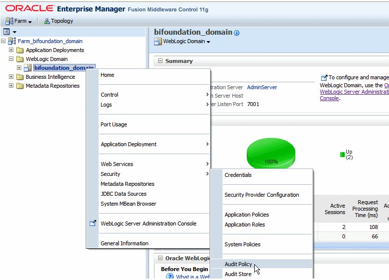
c. To set the Audit Level for BI Publisher, choose Medium from the Audit Level drop down menu or choose Custom to enable individual components. For this exercise we choose Medium.
4. Restart WebLogic Server
Restart the WebLogic Server using Fusion Middleware Control.
After restart the Audit information will be available in /AdminServer/logs/auditlogs/xmlpserver/audit.log. Create few reports and notice the audit logs in the file. Now we can create and configure audit repository to store the logs in database table instead in log files. Reports can be built over these tables to monitor.
5. Configure Audit Repository.
a. Create the audit schema using RCU (Repository Creation Utility – a separate package required for along with the OBIEE 11.x package)
                                  i. Run rcu.bat from RCU_HOME/bin
                                 ii. Follow the installation wizard and select Audit Services as show below.
                              iii. Continue the wizard and click Finish.
                             iv. As show below three schemas will be created for audit by the installation.
1. OBI_IAU
2. OBI_IAU_APPEND
3. OBI_IAU_VIEWER
6. Create a Data Source in WebLogic Server
To access the database schemas that we have created above we need to create a JDBC connection on the WebLogic Server. So that Audit Framework can access the schemas. Following are the steps to create a JDBC connection using Oracle WebLogic Server
a. Login to WebLogic Server Administration Console
b. Under Services, click Data Sources.
c. Click Lock and Edit button to enable editing.
d. On the Summary of JDBC Data Sources page, click New and click Generic Data Source.
e. Enter the following details for the new data source;
                           i. Name (example: BIP_AuditDB)
                          ii. JNDI Name (example: jdbc/AuditDB)
                         iii. Database Type (example: Oracle)
f. Click Next and select the database driver “Oracle's Driver (Thin XA) Versions: 9.0.1 or later” for Oracle database.
g. Enter the required connection properties like Database name, host name, port, database user name (for our exercise it’s OBI_IAU) and the password.
h. Click Next and accept the default setting and then click Test Configuration button as show below.
i. If the connection was successful, click Activate Changes to make the changes available.
7. Register the Audit-Storing Database to your Domain
a. Login to Fusion Middleware Control
b. Navigate to the WebLogic Domain, right click bifoundation_domain, then select Security, then Audit Store
c. Click Search Data Sources. From the Select Data Source dialog, select the data source you created and click OK
d. Click Apply and restart the WebLogic Server.
Note: After the restart, BI Publisher will store all auditing data into the database table called "IAU_BASE". To verify this procedure, try logging in to BI Publisher and opening a few reports. You should see the activity audited in the "IAU_BASE" table. If not, check the log file, which is located at: $BI_HOME/user_projects/domains/bifoundation_domain/servers/AdminServer/logs/AdminServer-diagnostic.log.
With the above data in IAU_BASE you can design the auditing reports using BI Publisher.
8. Create Auditing Reports
Following are the few steps in brief assuming the user knows about creating reports in BI Publisher in detail. 
  a. Create data source in BI Publisher
      Register the audit data source (JNDI/JDBC connection) that you created in the previous procedure as a JNDI data source in BI Publisher. Because you created a JDBC connection registered as JNDI, you do not need to create a new JDBC connection by typing the connection URL, username/password, and so on. You can just register it using the JNDI name (for example: jdbc/AuditDB).
           i. Log in to BI Publisher with administrator privileges and click the Administration link.
          ii. Under Data Sources, click JNDI Connection, and then click Add Data Source.
         iii. Enter the Data Source Name and JNDI Name. The JNDI Name is the name you provided       in the WebLogic Console as the auditing data source (for example: jdbc/AuditDB).
        iv. Click Test Connection to ensure that the data source connection works.
          v. Add the appropriate roles to the data source so that the report developers and consumers         can view the reports built on this data source. Click Apply to save.
b. Create (advanced) auditing reports for OBIEE version 11.1.1.5
With the version 11.1.1.5, we can make use of xmlpserver_audit.sql script to create a new table XMLPSERVER. Following are the steps;
                                                  i. Locate the table creation script xmlpserver_audit.sql at /user_projects/domains/bifoundation_domain/config/bipublisher/repository/Admin/Audit
                                                 ii. Edit the PERMISSIONS and SYNONYMS sections of the script as shown below.
From:
To:
                                               iii. Execute the updated script to create a new table and in OBI_IAU schema that you have created. You can login as SYS and alter the session to execute on OBI_IAU schema.
                                             iv. Restart the WebLogic Server.
                                              v. Create few sample reports in BI Publisher and notice the auditing information in the new table XMLPSERVER which will be used for building advanced BI Publisher auditing reports.
c. Create a data model
                                              i. Create a new data model with JNDI as the default data soruce.
                                            ii. Build or apply the following query using IAU_BASE table from OBI_IAU schema.
select
IAU_BASE.IAU_COMPONENTTYPE as IAU_COMPONENTTYPE,
IAU_BASE.IAU_EVENTTYPE as IAU_EVENTTYPE,
IAU_BASE.IAU_EVENTCATEGORY as IAU_EVENTCATEGORY,
IAU_BASE.IAU_TSTZORIGINATING as IAU_TSTZORIGINATING,
to_char(IAU_TSTZORIGINATING, 'YYYY-MM-DD') IAU_DATE,
to_char(IAU_TSTZORIGINATING, 'DAY') as IAU_DAY,
to_char(IAU_TSTZORIGINATING, 'HH24') as IAU_HH24,
to_char(IAU_TSTZORIGINATING, 'WW') as IAU_WEEK_OF_YEAR,
IAU_BASE.IAU_INITIATOR as IAU_INITIATOR,
IAU_BASE.IAU_RESOURCE as IAU_RESOURCE,
IAU_BASE.IAU_TARGET as IAU_TARGET,
IAU_BASE.IAU_MESSAGETEXT as IAU_MESSAGETEXT,
IAU_BASE.IAU_FAILURECODE as IAU_FAILURECODE,
IAU_BASE.IAU_REMOTEIP as IAU_REMOTEIP
from
OBI_IAU.IAU_BASE IAU_BASE
where
IAU_BASE.IAU_COMPONENTTYPE = 'xmlpserver'
To create a data model that contains only the BI Publisher data, then you can filter the data based on the value of the IAU_COMPONENTTYPE column that contains the product name. For BI Publisher, the value is "xmlpserver"
                                          iii. Test the sample with Get XML Output and save XML to your data model.
                                        iv. Save the data model.
d. Create the reports
Use know techniques for creating BI Publisher layouts, this exercise is out of scope.
                                           i. Using the layout options create a new BI Publisher layout.
                                          ii. Select the data model you have created in the previous procedure.
                                        iii. Click Add New Layout and click Base Templates. Following is the sample report from the layout editor (from Oracle)
                                    iv. Below are few samples auditing report with the data from the newly created schemas. Use both IAU_BASE and XMLPSERVER tables to build advanced detailed reports.

Friday, June 24, 2011

DAC Reporting in OBIEE

The purpose of this blog is to show how to consume data in the DAC repository via OBIEE reports.

What is DAC?

Oracle Business Intelligence Data Warehouse Administration Console (Oracle DAC) provides a centralized console for schema management, configuration, administration, loading, and monitoring of the Oracle Business Analytics Warehouse. The Data warehouse Application Console (DAC) is used to create and schedule Informatica ETL workflows. It manages the following data warehouse load processes:
  • Dynamic generation of subject areas and execution plans
  • Dynamic settings for parallelism and load balancing
  • Intelligent task queue engine based on user-defined and computed scores
  • Index management for ETL and query performance
  • Embedded high-performance OTLP change capture techniques
  • Restart from any point of failure
DAC / ETL Statistics
The metadata for ETL is stored in the DAC repository that is composed of approximately 120 tables. These tables store the ETL metadata such as tasks, task steps, execution plan details, connection details, run history, etc.
In this exercise we are only interested in the run history table - W_ETL_DEFN_RUN. This table has the ETL execution details for every Execution plan that was run through DAC (see screenshot below).

We will be walking you through the steps for creating a simple solution that will allow you to analyze the metadata in W_ETL_DEFN_RUN in OBIEE.
RPD
Below is a simple RPD model that is based on the single W_ETL_DEFN_RUN table from the DAC repository.
Reports
Using the subject area (Statistics – ETL) shown above, you can build useful reports to analyze the execution history (for each execution plan type).
1. Current month summary view with duration in minutes & hours.
2. Snapshot of run duration for each month.
Notice the failed steps in orange below.
3. Report showing Error / Status description with number of steps – Total, Failed, and Success.
4. Compare the ETL for large duration (2010 and 2011).
By adding other repository tables into your RPD you will be able to develop more sophisticated reports. You can even have error reports delivered to you with iBots whenever ETL errors occur.

Friday, June 17, 2011

Informatica - Beyond ETL

Informatica has long been one of the business intelligence / data warehouse industry leaders in data integration. Its PowerCenter and PowereExchange products have consistently been positioned in the leader quadrant for data integration by Gartner. However, Informatica is not resting on its laurels. Since 2009 Informatica has gone on an acquisitions rampage buying up best in breed companies with similar data-centric DNA while at the same time continuing to innovate and broaden its base products. The Informatica Platform now enables you to integrate data within the traditional enterprise (Enterprise Data Integration), control data in the clouds (cloud data integration), share data with your partners (B2B Data Exchange), archive data for efficiency and eDiscovery (Application ILM), and deliver data at zero latency (Ultra Messaging). To unlock the business value of all this data, the platform enables you to cleanse and gain trustworthy data (Data quality), to detect and act on operational intelligence (Complex Event Processing) and gain a 360 view of your strategic, authoritative master data assets (Master Data Management).

Informatica’s CEO stated that “only Informatica delivers the comprehensive, unified and open data integration platform to empower the data-centric enterprise.”


Clearly, Informatica has moved beyond ETL to embrace these key data-centric technologies.

Acquisitions since January 2009:
  • Applimation (Jan. 2009) – Leader in Application Information Life Cycle Management. Helping Customers manage their data assets from cradle-to-grave:

  • Data Archive for storing inactive and rarely accessed data on lower cost storage medium.
  • Data Privacy for masking identifying and identity data to remain in compliance with today’s stringent personal information and privacy laws.
  • Data Subset for creating purpose-built data sets for environment (DEV/QA/SYSTEM) or functional (CRM/ERP/FINANCE/HR) based testing.
  • Address Doctor (Mid-2009) – Leader in Worldwide Name and Address Validation for Over 200 Countries. Providing Customers with the highest quality name and address content for name and address standardization and validation.
  • Agent Logic (Oct. 2009) – Leader in Complex Event Processing and Operational Intelligence. Helping Customers institutionalize event detection patterns and human analysis patterns into automated opportunistic action and response alerts.
  • Siperian (Jan. 2010) – Leader in Master Data Management. Helping Customers achieve mastery of a single view of ‘X’ across all mission critical data domains.

Wednesday, June 8, 2011

Data Modeling: Schema Generation Issue with ERwin Data Modeler 7.3

We are using Computer Associate's ERwin Data Modeler 7.3 for data modeling. In one of our engagements, we are pushing data model changes to the physical database (Oracle 11g R2) via ERwin's Forward Engineering / Schema Generation functionality.


The Forward Engineer / Schema Generation wizard offers the "Physical Order" option under "Column". Checking this box is supposed to force the ERwin DDL generation engine to preserve the column order (i.e. the column order in the physical database must match the column order in the logical/physical model).

Problem: Even though our data modelers pay very close attention to the column order in the logical and physical model in ERwin, the Forward Engineering / Schema Generation process seems to lose the physical column order when generating the DDL (even though the "Physical Order" option is checked). Thus, the column order in the Oracle database never matches with the column order in the ERwin data model.

Solution / Work-Around: This is a bug as the behavior of this option seems to be inverted. If you want to preserve the column order, the "Physical Order" must be un-checked.

Friday, June 3, 2011

Upgrading to Informatica PowerCenter 9.1 from Version 8.6

We have completed the upgrade from Informatica PowerCenter 8.6 to PowerCenter 9.1. The Informatica Upgrade Guide for PowerCenter 8.5.x and 8.6.x describes an in-place upgrade of an existing hardware and software environment. However, as we wanted to upgrade our hardware at the same time, our plan was to setup a brand new Informatica PowerCenter 9.1 environment and import the code from our legacy PowerCenter 8.6 server.

Installing Informatica PowerCenter 9.1 on a Windows 64-bit server was straight forward but we ran into the following two issues:
  1. There seems to be a bug in the Pre-Installation System Check Tool (i9Pi). The purpose of this tool is to check that the server meets all installation requirements. This tool kept raising the following error “Make sure that open cursors are at least set to 1000” for our repository connection information to our Oracle 11g database. Even after our DBA had set this value to 1500 and restarted the Oracle 11g database service, the Pre-Installation System Check Tool continued to raise this error. This seems to be a bug in i9Pi because the installation was able to complete successfully.
  2. If you are planning on running Informatica PowerCenter 9.1 on a Windows platform, please be aware that Informatica has released an Advisory for Windows 32-bit Server and 64-bit Server Platforms. Informatica has identified problematic behavior of the PowerCenter Server, which a user would observe when monitoring multiple concurrent tasks from PowerCenter Workflow Monitor. This behavior is tracked as CR 252994 within Informatica’s bug tracking system. Informatica has released an emergency fix that can be downloaded at the following location:
After installing Informatica PowerCenter 9.1 and starting the service, one has to log into the Administration console (http://server-name:6008) and create the Repository Service and the Integration Service. Once done, install the Informatica PowerCenter 9.1 Client on a client workstation and re-create all Connection information in Workflow Manager. This is a critical task because dependent objects cannot be validated during import without having all corresponding source and target connections defined.

Export all Informatica content from the legacy 8.6 environment into an XML file and import it into the Informatica PowerCenter 9.1 environment with Workflow Manager (Repository ==> Import Objects). After this, we were able to run the imported code in version 9.1 without problems.
Please let us know about your experiences with upgrading to PowerCenter 9.1.

Friday, May 27, 2011

How-To: Creating a Universe with the BO XI 4.0 Information Design Tool

The following describes the steps to create a universe with SAP BusinessObjects XI 4.0's new Information Design Tool.


We would like to start with a graphic displaying a systematic method to create universes in the new tool.


Figure 1: Universe Creation Flowchart for the Information Design Tool

There are a few new terms that may jump out as you are reading this, but in case you have not noticed them, let's take a minute to list those terms out:

  • Connection – define how a universe connects to a relational or OLAP database. Local connections are stored as .CNX files, and secure connections are stored as .CNS files.
  • Data Foundation – a schema that defines the relevant tables and joins from one or more relational databases. The designer enhances the data foundation with contexts, prompts, calculated columns, and other SQL definitions. The data foundation becomes the basis of one or more business layers.
  • Business Layer – the universe under construction, and when the business layer is complete, it is compiled with the connections or connection shortcuts and data foundation, published, and deployed as a universe.
  • Universe – the compiled file that includes all resources used in the definition of the metadata objects built in the design of the business layer.

Each of the items above refers to a resource that can be stored in a Project when developing in the Information Design Tool. A project is a named local workspace that contains one or more resources used to build universes. Projects can be shared so that multiple designers are able to work on the same resources.

Step 1: Open the Information Design Tool. The new interface screen will be displayed.

NOTE – All created resources will be labeled as "TestProject[resourceType]", i.e. "TestProjectConn" for Test Project Connection.


Figure 2: New Interface Screen

Step 2: Create a new Project by clicking on File->New->Project.


Figure 3: Create Project Option

A local project must exist to assign resources; otherwise an error message will be given.


Figure 4: Sample Error if no local project exists


Figure 5: New Local Project Created

Step 3: Create a new Connection. Right-click on the project you just created, or use "File->New" and choose the Relational Connection or OLAP Connection.

For the purpose of this entry, we will be creating a Relational Connection.


Figure 6: Choose a Connection


Figure 7: Define a name for Connection

Step 4: Select the proper Database Middleware driver and configure the connection. The tool comes equipped with several DB driver connections with a default installation.

Note – You must have proper privilege to the schema you are accessing. Also, an ODBC or OLE DB connection must already be established to function properly.


Figure 8: Choose the Middleware Driver


Figure 9: Connection Configuration 1


Figure 10: Connection Configuration 2


Figure 11: Connection Configuration 3


Figure 12: New Local Connection Created

A new connection should now be present and expanded in the project. This connection remains local to the project. Connections to be used in published universes will need to be published to the repository and saved as secure connections.

Step 5: Publish the connection to the repository as a secure connection. Right-click on the new local connection, or highlight the connection and choose the "File->Publish->Publish Connection to a Repository" option.


Figure 13: Publish the Connection to a Repository


Figure 14: Secure Connection Shortcut Established

Step 6: Create a new Data Foundation and configure the Data Foundation. Right-click on the project you created, or use the "File->New->Data Foundation" option.


Figure 15: Data Foundation Configuration 1

Note – there are two types of data foundations: Single-Source and Multisource-Enabled.

Single-Source

  • Support a single connection.
  • The connection can be local or secured, which means you can publish universes based on the data foundation either locally or to a repository.
  • Recommended for the following situations: you want to work exclusively with database-specific SQL syntax, or you want to publish the universe locally and work outside of a repository.
Multisource-Enabled

  • Support one or more connections.
  • You can add connections when you create the data foundation and anytime later.
  • Multisource-enabled data foundations only support secured connections, and universes based on this type of data foundation can only be published to a repository.
  • Required for the following situations: you want to insert tables and joins from more than one relational data source, you want to insert tables and joins from more than one relational data source, or you want to use SQL-92 syntax and SAP BusinessObjects SQL functions.


Figure 16: Data Foundation Configuration 2

Step 7: Select the Connection to associate to the Data Foundation.


Figure 17: Data Foundation Configuration 3


Figure 18: Data Foundation Created

Step 8: Choose the Tables to Insert. You also have an option to insert Derived Tables and Views as well.

Note – Joins to objects in the Data Foundation can either be detected or manually inserted.


Figure 19: Insert Tables for Data Foundation 1


Figure 20: Insert Tables for Data Foundation 2


Figure 21: Data Foundation Created

Step 9: Create a Business Layer. Right-click on the project you created, or use the "File->New" and choose the Relational Business Layer or OLAP Business Layer. The type of business layer depends upon the connection that you used for the Data Foundation.


Figure 22: Business Layer Configuration 1

Step 10: Select the Data Foundation that you would like to use as the basis for the business layer. The tool also provides the option to automatically create classes and objects based on the Data Foundation Layer.


Figure 23: Business Layer Configuration 2


Figure 24: Business Layer Created


Step 11: Publish the Universe to the Repository. Right-click the Business Layer and choose the "Publish->To a Repository" option. This will save the Universe as a .UNX file.

Note – Ensure the Connection for the corresponding Data Foundation is a Secure Connection.


Figure 25: Publish Universe 1


Step 12: Execute a Universe Integrity Check and ensure critical errors are resolved.


Figure 26: Publish Universe 2


Step 13: Choose the Repository Folder to store the Universe.


Figure 27: Publish Universe 3


After clicking the "Finish" button, the Universe is successfully published and ready for use by the users.


Figure 28: Universe Published


You can verify that the Universe is available by logging into Interactive Analysis and creating a new document.


Figure 29: Universe Available for use in Interactive Analysis


This concludes the guide to create a Universe using the Information Design Tool. As you can see, some new terminology has been added along with a different approach to create an entire universe. We feel that the new layout and approach is tailored for multiple information designers to work on specific resources. Even though no official statement has been made by SAP BusinessObjects, we believe that the Information Design Tool will become the eventual successor to the Universe Design Tool.